Binary Clock Project

All three versions on one photo

click for full size image!

1st

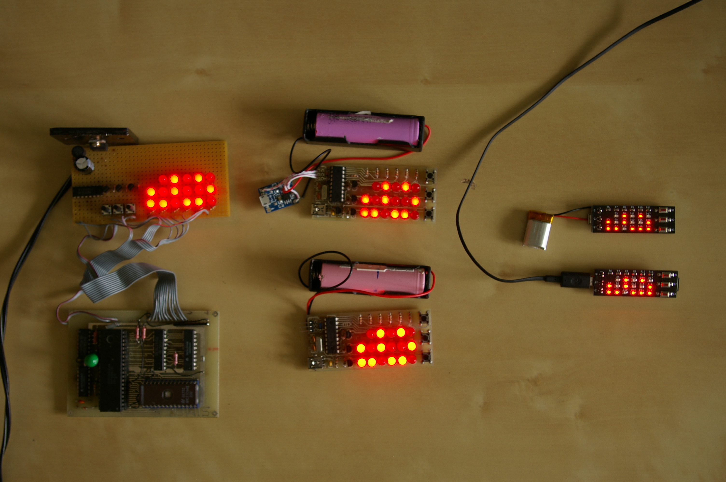
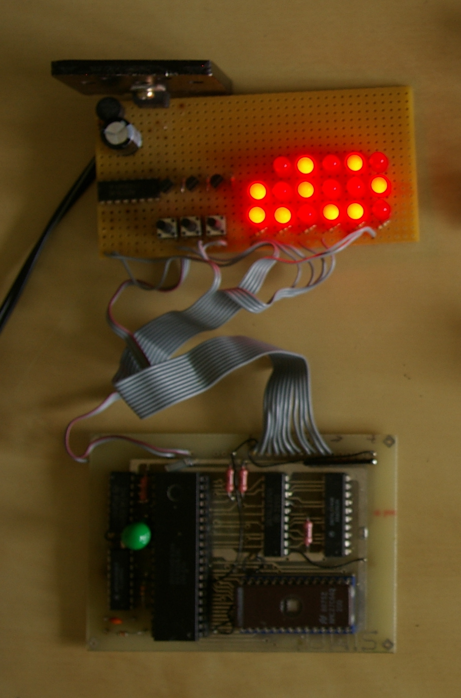
Date: 2011 - 2012. What can I do with my old Z80 board, which I bought in the late 80s? I ordered this panel from the 'Mikroszamitogep Magazin 1987/8'. You can read all the three pages about the board here, here, and here. I modified the board a little bit: i.e. I changed the output latch (74LS273) to another one (74LS374)

The main problem with this board was that it has only eight outputs. How can I control directly 17 LEDs on 8 bits? If I make a compromise, and the clock will not be able to show 24 hours (only 12), then the 8 bits would be enought for 16 LEDs in a 4x4 matrix. But I wanted a 24 hours display! So I had to extend the 8 bits. The lower 6 bits were the digits, and the higher 2 bits ensured the row control. To extend 2 bits to 3 rows, I used an external demultiplexer circuit (74LS138).

In this clock I did not use quartz crystal controlled oscillator. The Z80 has a non maskable interrupt, which I can activate at the corresponding pin. So I connected the power mains 50 Hertz to this pin. This frequency is precise enough in Hungary.

Lastly, I had to burn the self-depeloped program into an EPROM (27C64). I had only two empty EPROMs, and I did not have an eraser for them (just an old burner). But the Z80 developer and simulator program is great, I could make a working code with it. The first version had a little bug (did not reset itself at midnight). But the second EPROM worked perfectly.

click for full size image!

2nd

Date: 2013. The Z80 processor has a very bad 'feature': It needs a high amount of current, more than 100 mA (if I calculate with 114 mA, it means 1 kWh / year). And of course it is big, hard to change its program in the EPROM, etc... So, I looked for a more lightweight solution. The PIC 16f628 is an ideal choise. Its consumption is less than 1 mA.

The clock circuit and PCB is my own plan, I draw and constructed them in the KiCad EDA software. Then I sent the special output files (gerbers) to a factory (firstly here), which created the printed circuit boards perfectly.

The firmware of the clock is made in assembler language in the same software package, which I bought from Oshonsoft. The microcontroller programmer was an old K150 based circuit.

I made also a DIY page if someone wants to build this board.

For the newest firmware version I made a limited amount of black panel, see it at the right side of this section

click for full size image! click for full size image!

3rd

Date: 2019. After 6 years I thought, that I can make this circuit much smaller. The microcontroller remained the same (but with different package), and the circuit changed a little bit only. For example, I placed a reference voltage diode, with which the processor can check the voltage of the battery with its analogue comparator. When the battery voltage discharges to about 3.5 V, the clock switches to a power saving mode: only one LED is blinking with less intensity. The clock can work in normal mode cca. 3 month with a 18650 type battery without charging it. I put a li-ion charger to the board too with a couple protector diodes. The processor, crystal, charger and some other components sit on the back side of the PCB. All components are smd type, so the fine and precise handsoldering is not so easy.

The firmware has been updated according to the new hardware features. There is a new software feature too. With this new feature the clock can correct the crystal inaccuracy from +- 60 msec to 7.2 sec per day in 60 msec steps.

And the size of the final version has become smaller, because I used smaller buttons and pre-biased transistors (so I could omit three resistors from the board).

click for full size image! click for full size image!