Build a brand new computer from a blank PCB

click for full size image!

This is a totally useless project; I already have a working machine, some components are very expensive, and hard to purchase some of them.

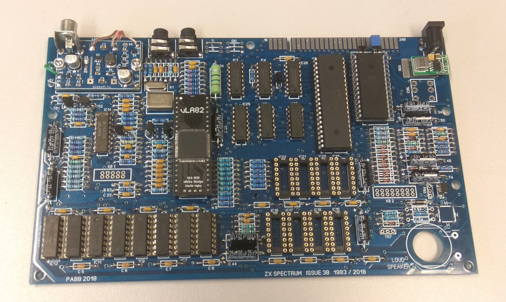
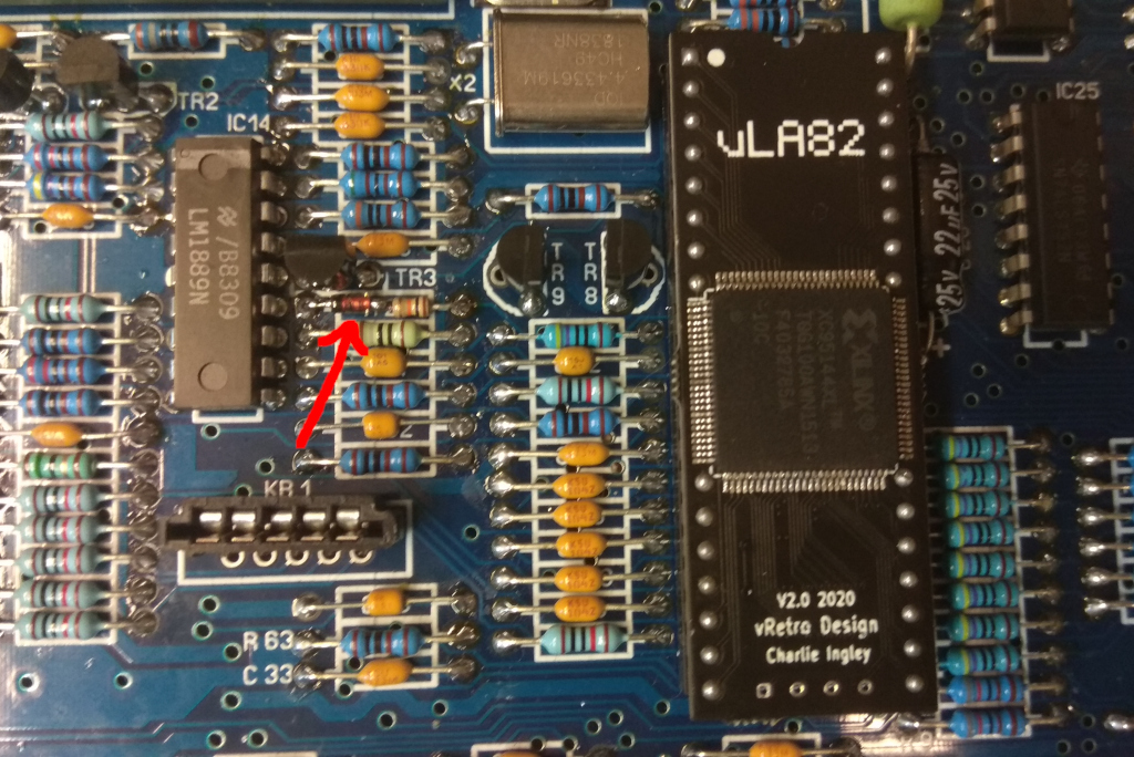
However it is very exciting! For example the ULA came from the other side of the Earth (form New Zealand), the axial capacitors came form another side of the Earth (form USA), and there are some factory nowadays, which produce the mechanics (PCB, case and keyboard components).

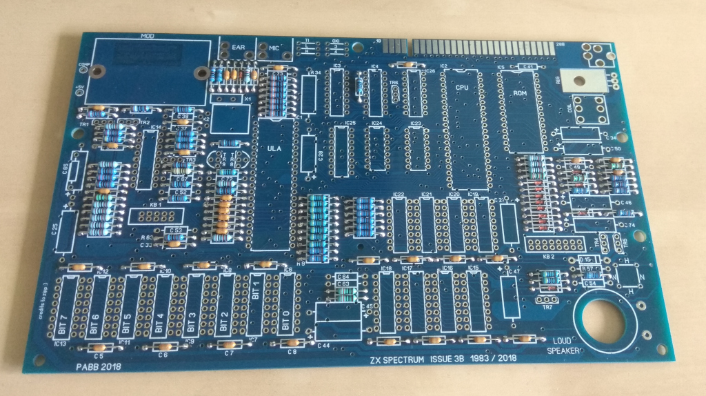
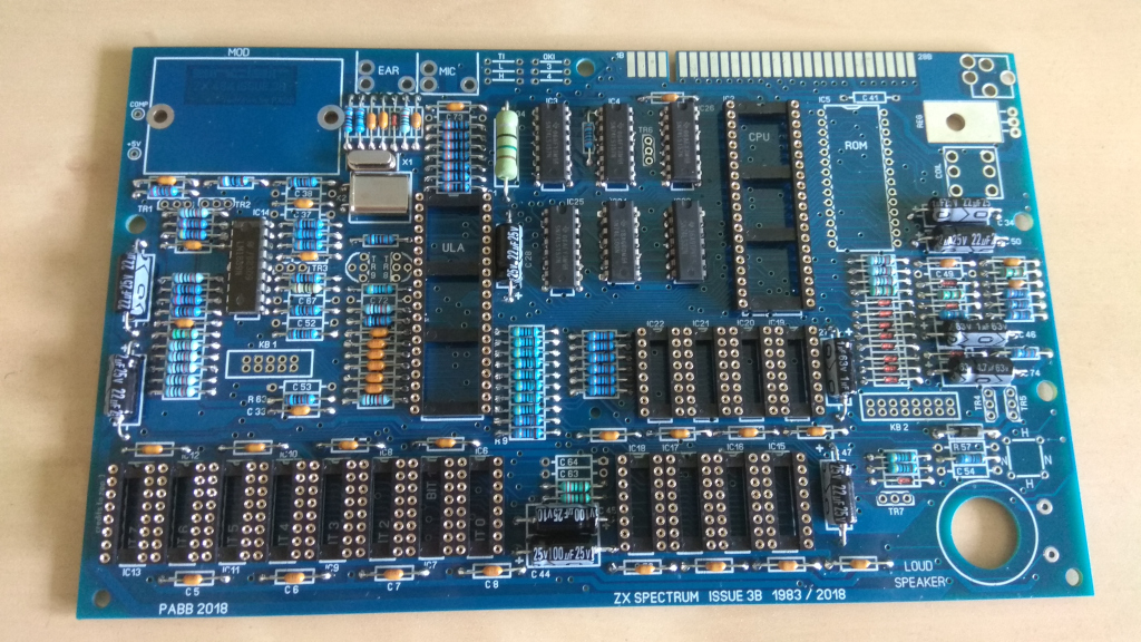
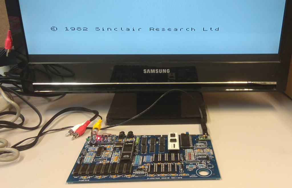
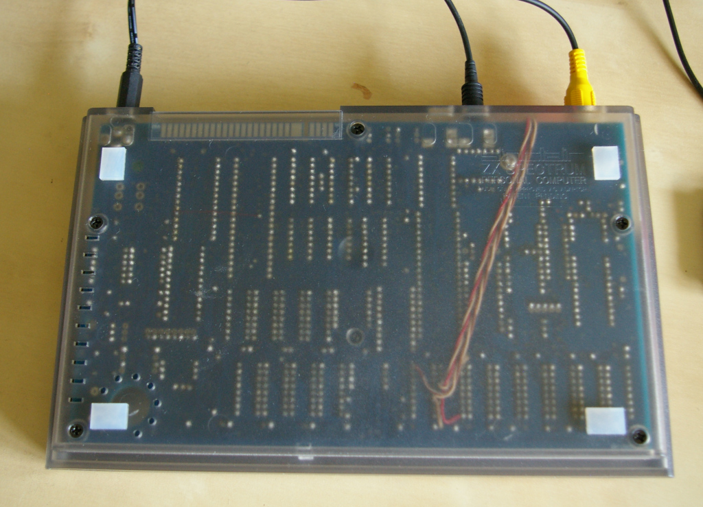
These pictures show the phases of the build.

click for full size image! click for full size image! click for full size image!

When I turned on firstly the board then it was not worked of course... The main problem was, that the low level of the ULA clock generator output was too high (0.7V), so the transistor - which got this sign - was always open. My solution is a serial diode with the base resistor (red arrow shows it in the picture). Another problem was the Z80 processor, which is not worked, I do not know why. But with a special processor board - which contains a Z80 processor plus 32kbyte RAM -, the computer started immediately (update: the processor was faulty :-( ).

The third picture shows the bottom side of the assembled machine. You can see a 4 wire cable, which provides the power supply for the 4116 type RAMs from my own developed circuit board. I developed a special ROM socket too, which can handle 4 selectable ROM images.

And of course I left out the heater 7805, I put a step down switching unit instead of it.

click for full size image! click for full size image! click for full size image!

A few month later I assembled an other computer with purple colour. I ordered this PCB from the manufacturer directly, but I edited the drill file before I rent the production. Two problems were with the blue board: 1. all TH and VIA diameters were greater than 1mm (I think it is unnecessary), so I modified them to 0.8mm. With this modification the soldering surface of the pads will be a little bit larger and thus stronger. 2. the jack holes are too tight on the blue board, I had to cut the pins of the jacks, so I increased the size of the jack holes.

In these photos you can examine my two special circuit. One of them is a special PROM socket. With this socket I can use 5 types of PROM for the computer (original ZX-Spectrum ROM, 27C128, 27C256, 28C256, 27C512). With the largest type I can select 4 different ROM with jumpers at the top of the board. The another board is a video output circuit combined with a +12V, -5V power supply. It is replaced the original modulator.

click for full size image! click for full size image! click for full size image!